Whenever possible, Tux-Lab uses Open Source Software.
Jan 22, 2013
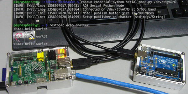
Installation notes for connecting Arduino to Raspberry Pi via rosserial.
Two available tutorials were used for reference. The first tutorial goes over installation of Fuete ROS on a Debian, and the second tutorial is specifically for RPi installation.
The above tutorial were followed to just before building Layer 2 (Higher-level robotics libraries and tools) due to rosdep install -a errors. Subsequently, rosserial package containing rosserial_arduino was manually built and installed
There were a few deviations from the above tutorials and they are as follow:
- Used sudo pip install -U rosdep==0.10.08 to avoid later rosdep installation errors
- sudo aptitude install libeigen3-dev, libcppunit-dev, python-sip-dev, python-serial for additional dependencies required for rosserial installation.
- Created a workspace to manually download and build rosserial and related packages.
- rosws init ~/fuerte_workspace
- source ~/fuerte_workspace/setup.bash
- download and build the the following ROS packages,
- bullet, kdl, tf, rosserial
- The steps used to download and build each package.
- roslocate info package_name > package_name.rosinstall
- rosinstall ~/fuerte_workspace package_name.rosinstall
- source ~/fuerte_worksapce/setup.bash
- rosmake package_name
- For tf package, use the fuerte_devel version by editing tf.rosinstall
To bypass SSL certificate error during rosinstall, edit the package_name.rosinstall and change uri from https to http.
Arduino was running a publisher program uploaded from a PC with ROS and Arduino IDE installed following another ROS tutorial. Command line usage of ROS/Arduino upload is possible.

Jan 20, 2013
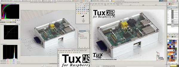
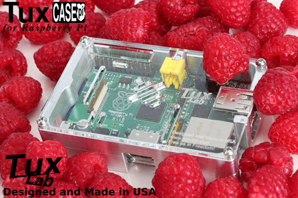
The last step of the product development process is creating the promotional photos for retail sales. Photos are taken with a dslr camera in its native raw format and post processed in URaw before exporting to GIMP for the final re-sizing and adding graphics elements.
After the first set of photos were taken, there was a compatibility issue between UFRaw and Canon T2i so second set of photos were taken with a Canon 5DMk2.
Jan 19, 2013
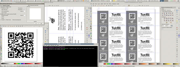
The 2" x 4" product label was also designed with Inkscape. The embedded QR code was first generated with command line qrencode then imported into Inkscape. Originally, the QR code image was generated in PNG format then automatically traced with Inkscape's Trace Bitmap command. However, qrencode can also generated QR code in EPS format without the need for trace conversion.
Jan 17, 2013
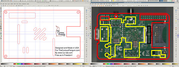
Inkscape was used to design the acrylic components for laser cutting and engraving. Earlier Raspberry Pi boards do not have mounting holes. Therefore, an acrylic floor is used in place of machined standoffs.
The top cover profile was based on the 2D dxf drawn earlier with LibreCAD. GPIO and venting openings were added in Inkscape. For the acrylic standoff, the profile was also based on the 2D dxf drawing. The back of the Raspberry Pi pcb was scanned, then rotated and resized in GIMP before importing into Inkscape. The cutout for the bottom components were added in Inkscape using the scanned pcb image as reference.
A few design iterations were needed to get the dimensions right, especially for the floor board. The acrylic thickness is .118" and is tall enough to ensure none of the bottom solder leads contacts the aluminum case.
Jan 15, 2013
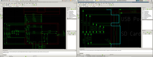
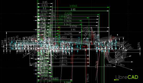
LibreCAD was used to generate the dimensional drawing for TuxCASE_pi. The case dimensions are necessary for writing the G-code program that will will be used by the CNC controller to machine the aluminum block into the final shape of TuxCASE.
LibreCAD was also used to layout the extra tool paths that are needed. For example, the SD Card and USB Power slots are too deep for the 3/8" end mill to machine effectively in a single pass. Therefore, a couple extra machining passes are needed. Those extra tool path are generated with LibreCAD's line offset tool.
Jan 14, 2013
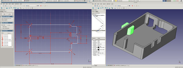
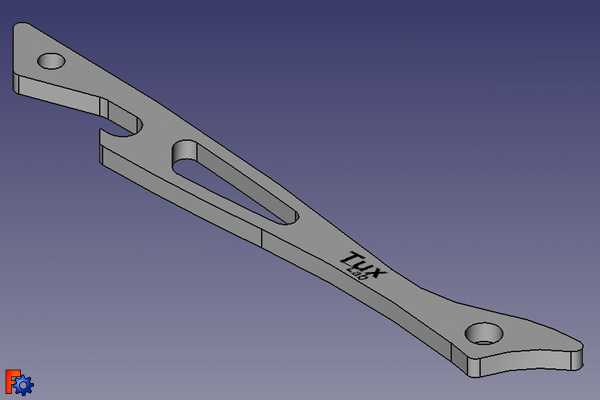
The 3 dimensional model of TuxCASE for Raspberry Pi was made with FreeCAD for visual inspection. The open source FreeCAD follows a workflow similar to commercial software where 2 dimensional drawings are turned into 3 dimensional shape through basic extrude operation. Multiple 3 dimensional object can then be combined or subtracted to construct the final 3D model.
The 2D drawing from FreeCAD can also be exported as DXF to be opened in LibreCAD for tool path calculation.
Note: Currently, FreeCAD v13r1335 is metric only. However, LibreCAD can convert the FreeCAD generated DXF file from millimeter to inch.

May 16, 2012
Apr 23, 2012
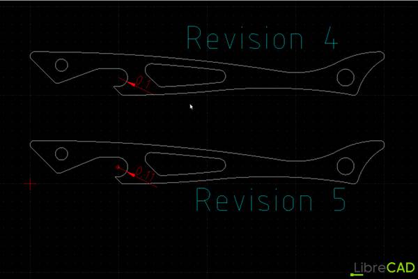
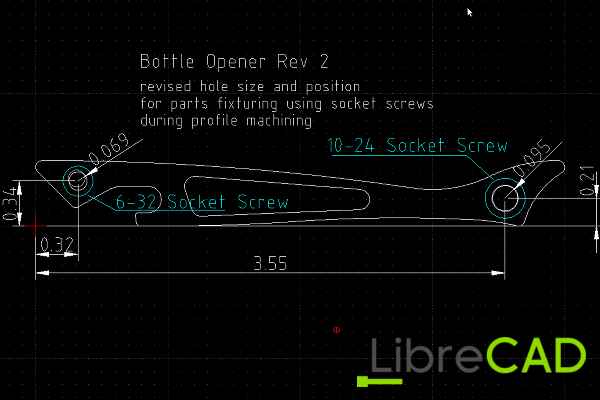
The shallow mouth opening has too steep of an angle and tends to peal the cap back. The mouth opening was elongated to give better leverage to lift the cap.
Apr 06, 2012
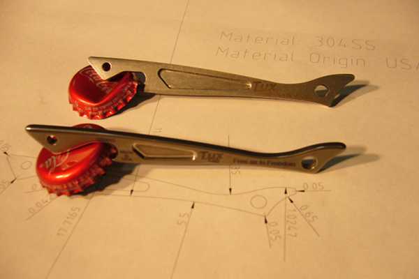
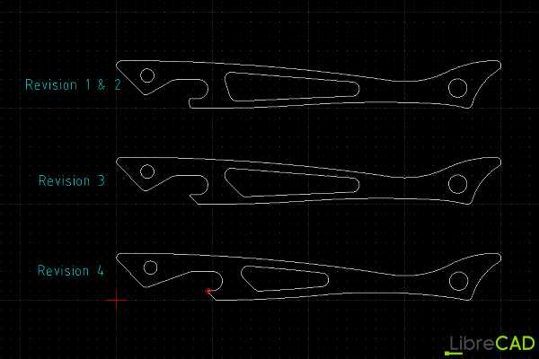
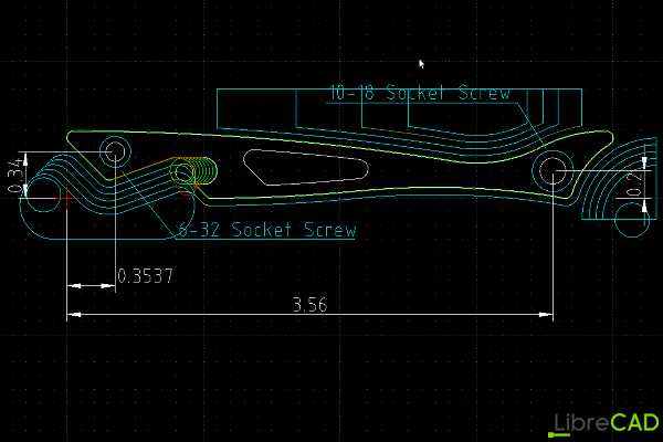
Modify radius and location of head and tail holes for fixturing with socket screw during op3, machining of the profile.
Apr 04, 2012
Before the g-code can be written, the machining tool path needs to be determined. A total of 3 cutting tools will be used. A shell mill to smooth both the top and bottom, a .25" end mill will perform most of the rough profiling, and a .125" end mill will perform the final profiling pass.
Each cutting tools has a specified cutting parameter. For both the .25" and .125" end mill the recommended radial cutting depth is 20% of tool diameter. Base on this information, LibreCAD was was to draw out the tool path.
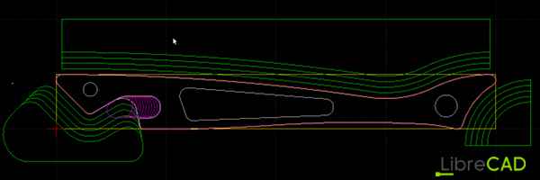
In g-code, the tool path is represented by a series of linear and circular moves. Each transition point, ie where straight line meets a curve or where curves of different radius meets, on the tool path needs to be specified in terms of its X-axis and Y-axis coordinate. If the the next move is a circular move, the radius will also need to be specified. The process of dimensioning the transition points can be quite tedious.