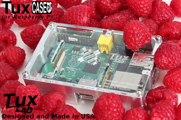
TuxCASE for Raspberry Pi
| - TuxCASE for Raspberry Pi Task Summary - | |||
| 3D model with FreeCAD | Completed | 4.0 hr | $0.00 |
| 2D drawing with LibreCAD | Completed | 4.0 hr | $0.00 |
| G-Code writing with Geany | Completed | 6.0 hr | $0.00 |
| CNC Machining | Completed | 12.0 hr | $0.00 |
| Cover & Floor Plate Design | Completed | 4.0 hr | $0.00 |
| Laser Cutting | Completed | 2.0 hr | $0.00 |
| Label Design with Inkscape | Completed | 2.0 hr | $0.00 |
| Product Photo with UFRaw & GIMP | Completed | 5.0 hr | $0.00 |
| Modification for MicroSD Adapter | Completed | 2.0 hr | $0.00 |
| Mounting Hole Standoffs | Planned | 2.0 hr | $0.00 |
Jan 14, 2013
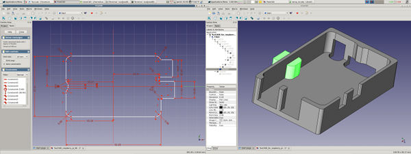
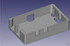
The 3 dimensional model of TuxCASE for Raspberry Pi was made with FreeCAD for visual inspection. The open source FreeCAD follows a workflow similar to commercial software where 2 dimensional drawings are turned into 3 dimensional shape through basic extrude operation. Multiple 3 dimensional object can then be combined or subtracted to construct the final 3D model.
The 2D drawing from FreeCAD can also be exported as DXF to be opened in LibreCAD for tool path calculation.
Note: Currently, FreeCAD v13r1335 is metric only. However, LibreCAD can convert the FreeCAD generated DXF file from millimeter to inch.
Jan 15, 2013
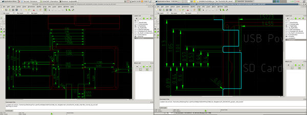
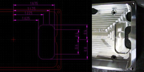
LibreCAD was used to generate the dimensional drawing for TuxCASE_pi. The case dimensions are necessary for writing the G-code program that will will be used by the CNC controller to machine the aluminum block into the final shape of TuxCASE.
LibreCAD was also used to layout the extra tool paths that are needed. For example, the SD Card and USB Power slots are too deep for the 3/8" end mill to machine effectively in a single pass. Therefore, a couple extra machining passes are needed. Those extra tool path are generated with LibreCAD's line offset tool.
Jan 16, 2013
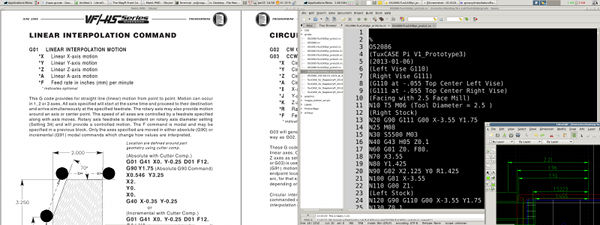
The G-code program is grouped by tools and each tools has sub sections representing a machining operation. For example, The first group of machining operation is performed by the 2.5" facing mill. The 2.5" face mill has two sub sections. First is the face milling of the bottom surface on the right vise and the second is face milling of the top surface on the left vice.
Machining Operations:
- 2.5" Face Mill
- Right Vise - Face bottom of case
- Left Vise - Face top of case
- 3/8" Roughing End Mill
- Right Vise - Profile bottom half of case
- Right Vise - Machine HDMI opening
- Right Vise - Machine Power and SD card opening
- Left Vise - Profile top half of case
- Left Vise - Machine pocket for RPi board [ tool path generated by VisualMill ]
- 3/8" Ball End Mill
- Left Vise - Machine RCA Video opening
- 5/16" Ball End Mill
- Left Vise - Machine Audio opening
- 3/8" 120 Degree Chamfer Mill
- Left Vise - Spot drill cover screw holes
- Left Vise - Chamfer top profile of case
- Right Vise - Chamfer bottom profile of case
- #43 Drill
- Left Vise - Drill cover screw holes
- 4-40 Tap
- Left Vise - Tap cover screw holes
- #32 Drill
- Left Vise - Drill bottom mounting holes
- 1/4" 100 Degree Chamfer Mill
- Left Vise - Chamfer bottom mounting holes
- 1/16" Ball End Mill
- Left Vise - Engrave Serial Number
Jan 16, 2013
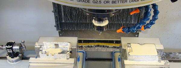
Usually a few machining iterations are required to proof the G-code program and to fine tune the machining parameters. TuxCASE for Raspberry Pi uses simple front and back operations to minimize setup cost. The machining operations use two Kurt D675 vises. There are cheaper alternatives, but the D675 manual vise is the least expensive of the domestically made machine vises. The left vise is for machining the top of the case and the right vise is for machining the bottom of the case. This setup allows for one complete case to be machined with each program cycle.
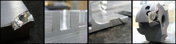
Sometimes, the tool path offsets are incorrectly calculated, or the tool length offset is too short for part, or the work piece was not clamped securely. Usually the part is scraped, but in some unfortunate events, the cutting tool is scraped.
Bellow are some of the unpleasant mishaps.
Jan 17, 2013
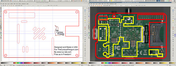
Inkscape was used to design the acrylic components for laser cutting and engraving. Earlier Raspberry Pi boards do not have mounting holes. Therefore, an acrylic floor is used in place of machined standoffs.
The top cover profile was based on the 2D dxf drawn earlier with LibreCAD. GPIO and venting openings were added in Inkscape. For the acrylic standoff, the profile was also based on the 2D dxf drawing. The back of the Raspberry Pi pcb was scanned, then rotated and resized in GIMP before importing into Inkscape. The cutout for the bottom components were added in Inkscape using the scanned pcb image as reference.
A few design iterations were needed to get the dimensions right, especially for the floor board. The acrylic thickness is .118" and is tall enough to ensure none of the bottom solder leads contacts the aluminum case.
Jan 18, 2013
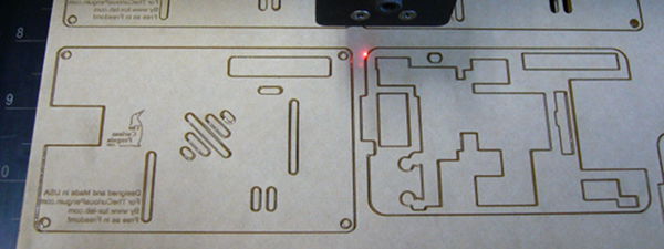
Compared to CNC machining, laser cutting has a shorter development time because the cut/engrave patterns are design in a free form drawing program(Inkscape) and interfaces with the laser engraver via the print function.
An ULS M300 35Watt CO2 laser engraver was used to cut and engrave the US made clear Acrylite FF extruded sheets.
Jan 19, 2013
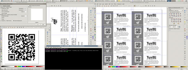
The 2" x 4" product label was also designed with Inkscape. The embedded QR code was first generated with command line qrencode then imported into Inkscape. Originally, the QR code image was generated in PNG format then automatically traced with Inkscape's Trace Bitmap command. However, qrencode can also generated QR code in EPS format without the need for trace conversion.
Jan 20, 2013
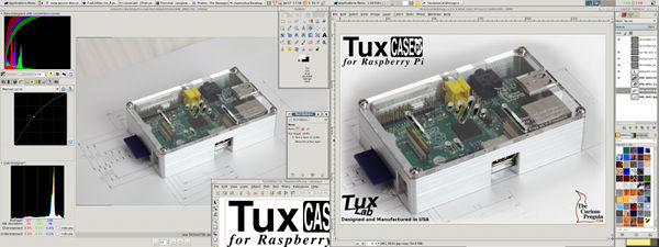
The last step of the product development process is creating the promotional photos for retail sales. Photos are taken with a dslr camera in its native raw format and post processed in URaw before exporting to GIMP for the final re-sizing and adding graphics elements.
After the first set of photos were taken, there was a compatibility issue between UFRaw and Canon T2i so second set of photos were taken with a Canon 5DMk2.
Jan 28, 2013
During the demo machining for the loal SGVLUG/SGVHAK, San Gabriel Valley Linux User group, the possibility of increasing the depth of the SD Card slot to accommodate half length micro-SD card adapter was mentioned.
After a quick modification in LibreCAD, a few extra lines of G-code was inserted and TuxCASE for Raspberry Pi project is now complete.
Feb 27, 2013


